MIDIO128 V3
Created in July 2011
The MIDIO128 application allows to midify keyboard instruments such as organs.
It can also be used for other purposes of course - whenever you are planning to trigger MIDI events with buttons, and/or to control LEDs (or relays) via USB, MIDI or Ethernet/OSC, have a closer look to the feature list!
While the previous version was based on the expired PIC based core, MIDIO128 V3 utilizes the new MBHP_CORE_LPC17 and MBHP_CORE_STM32F4 module, and provides much more features:
- up to 16 8bit input shift registers (=128 pins, =4 x MBHP_DINX4 modules)
- up to 16 8bit output shift registers (=128 pins, =4 x MBHP_DOUTX4 modules)
- up to 16 scan matrices for up to 1024 pins/keys
- up to 8 pots/faders directly connected to the core
- up to 128 pots/faders connected to up to two MBHP_AINSER64 modules.
- USB MIDI port with much higher transfer rate (ca. 100x faster!) than common MIDI
- Ethernet port to send/receive events via OSC
- support for DHCP - connect the module to a wireless router without additional configuration
- different OSC modes are prepared for popular PC/Mac/iPhone/iPad apps, extensions can be added on request
- can also be used as USB/MIDI interface, or even as OSC/MIDI interface
- integrated MIDI router with 16 configurable nodes
- multiple patches are stored on SD Card
- optional Control Surface for direct editing without a computer
- but patches can also be edited on a computer, e.g. in an Excel or Open Office spreadsheet
- integrated MIDI monitor for all Ports (USB/MIDI/OSC)
- integrated MIDI File Player and Recorder
- integrated SD Card Reader (Mass Storage Device driver for USB)
- more features available on request
 Hardware Hardware
The MIDIO128 V3 application consists of:
- a MBHP_CORE_LPC17 or MBHP_CORE_STM32F4 module
- up to 4 MBHP_DINX4 modules
- up to 4 MBHP_DOUTX4 modules
- an (more or less) optional SD Card
Without a SD Card patches can't be stored/restored, and MIDI files can't be played or recorded
- an optional 2x20 LCD + 6 buttons + detented rotary encoder for the control surface
Without the control surface patches can only be edited with a PC/Mac
- up to 8 pots/faders connected to J5A/J5B of the core module

Controlling Reed Relays
This diagram shows, how Reed Relays can be connected to the DOUT module.
This photo shows the circuit together with a 74HC595 shift register (DOUT) built on a veroboard.
Scan Matrices
MIDIO128 V3 allows to scan up to 16 8x8 matrices, which are connected between a DOUT and DIN shift register.
Connection diagram for a single matrix connected between MBHP_DIN and MBHP_DOUT module.
Connection diagram for two matrices connected to MBHP_DIO_MATRIX module.
Each matrix can be assigned to a dedicated DIN and DOUT shift register. Optionally it's possible to share a single DOUT register for all matrices (in this case assign a DOUT to the first matrix, and disable the DOUT for all other matrices). The remaining (not assigned) DIN/DOUT registers can still be used to connect buttons and LEDs directly.
Pots/Faders
Up to 8 pots/faders can be directly connected to J5A/B of the MBHP_CORE_LPC17 or MBHP_CORE_STM32F4 module as shown in the interconnection diagram.
The resistor value should be in the range of 1k..10k. The cable between pot and J5 port shouldn't be longer than 0.5m if 10k pots are used. With a shielded cable and 1k pots the allowed length is up to 2m.
More Pots/Faders
Up to 128 pots/faders can be scanned by using one or two MBHP_AINSER64 modules. The MIDIO128 firmware allows to configure individual MIDI events and Port routings for each analog input.
Installation
The MIDIO128 V3 firmware is released as a precompiled binary, which can be easily updated via USB MIDI by using MIOS Studio. Details about the bootloader are explained here.
Step by Step:
- it's assumed that you already tested the USB MIDI communication by pressing the Query button in MIOS Studio as explained in the Bootloader page - you should get some informations about the chip and the running application.
If this procedure sounds unfamiliar to you, please follow the hardware test procedure first as explained in the MBHP_CORE_LPC17 resp. MBHP_CORE_STM32F4 page.
- download the latest midio128_v3_* release package from the MIOS32 Download Page.
- unzip the .zip archive.
- load the project.hex file with the "Hex Upload" window of MIOS Studio and press the Start button.
- the new firmware will be transfered to your MIDIbox.
- once the "Upload completed" message is displayed by MIOS Studio (after ca. 20..30 seconds), your MIDIbox will reboot, and the new firmware will be started.
Working under Windows?
MIDIO128 enables 4 USB MIDI ports. Unfortunately some windows versions can't handle this correctly: MIDI is stucking sometimes, Filebrowser operations are failing, etc.
In order to overcome this issue, sometimes it helps to install the GM5 USB MIDI driver, which can be downloaded from the MIOS32 Download page.
Unfortunately the GM5 driver can cause new issues if multiple cores are connected. And users reported that it doesn't work stable under Windows XP. In such cases it's recommended to force the usage of a single USB port which solves the MIDI transfer issues with the drawback of the reduced functionality.
So: if you notice MIDI transfer issues, please enable the single_usb option with the MIOS32 Bootloader update application.
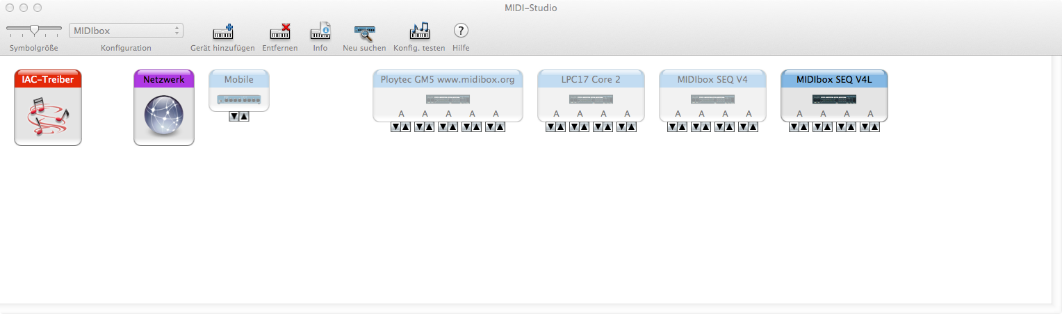
Working under MacOS?
The USB MIDI implementation of MacOS is perfectly working, regardless of the number of USB MIDI ports!
So far we only noticed a minor issue when an app changes the number of USB MIDI ports or the device name. Such changes won't be taken over automatically, instead you've to delete the old interface description in the Audio-MIDI-Setup:
- start the Audio-MIDI-Setup of MacOS (e.g. search for "audio-midi" with Spotlight)
- disconnect the core module from USB
- delete the interface in the Audio-MIDI-Setup
- connect the core module to USB again
Thereafter you should see an interface with the new names and the right number of USB MIDI Ports:
The Control Surface

The optional control surface allows to edit most configuration values without the need of a computer. The detented rotary encoder and buttons can be directly connected to J10 of the MBHP_CORE_LPC17, resp. J10A of the MBHP_CORE_STM32F4 module, no special DIN shift register is required (see also this schematic).
Meanwhile also a PCB is available which has been created by Ilmentator - see this Wiki page.
After startup the main screen will be displayed:

The upper line shows the current MIDI file once the soft-button below "PLAY" is pushed. The next two soft buttons allow to select the previous/next MIDI file found in the root directory of the SD Card.
By pressing the EXIT button (blue button in the picture) a second selection page will be displayed with some additional options:

The first Soft button allows to start/stop recording. The next two soft buttons to fast-rewind/forward the MIDI file. And the fourth soft button is doing nothing ;-) - to change the tempo (BPM), just rotate the encoder (works also when the EXIT button is not pressed).
By pressing the SHIFT button a special page will pop up:

- MIDI: allows to start/stop the MIDI file player from any page while pressing the SHIFT button.
- BPM: cycles between BPM Clock Auto/Master/Slave and Lock:
- Master: the MIDI player will run with a tempo specified in the .MID file
- Slave: the MIDI player is synchronized to an external (incoming) MIDI Clock
- Auto: the BPM generator is running in Master mode by default, but will switch to Slave mode when a MIDI clock is received.
- Lock: all MIDI files will play at the BPM rate specified in the main screen.
- DOUT: allows to disable all DOUT pins (like "All Notes Off") from any page
- MSD: enables/disables the Mass Storage Device driver as descriped in the "Integrated SD Card Reader" topic
Back to the main screen:
The fourth soft-button below "MENU" enters the configuration menu:

The pages are described in more details below.
Note that the 2x20 LCD will only display 4 of these items at once. Use the rotary encoder to scroll through the menu, and use a soft button to select the item above the button. Use the Exit button to get back to the previous page.
The DIN page:

allows to configure parameters for each individual input pin of the DIN shift register chain:
- Pin: the pin number counted from 0 (0..127)
- DIN: the same number in "SR.Dx" format: first number displays the number of shift register (counted from 1, 1..16), and the second number the data input of the shift register (D0..D7)
- Mode: the button behaviour can be configured in three modes:
- Normal: On-Event sent when button pushed, Off-Event sent when button depressed
- OnOff: only On-Event is sent, no event sent when button depressed
- Toggle: alternates between On- and Off-Event whenever button is pushed
- E0On..E2On: the three bytes of the "On-Event" which is sent when the button is pushed in hexadecimal format
- E0Off..E2Off: the three bytes of the "Off-Event" which is sent when the button is depressed (resp. Toggle mode: the alternate event) in hexadecimal format
- USB1..OSC4: selects the MIDI ports over which the selected DIN pin will send the MIDI event
Hot tip: the usage of this page is too cumpersome for "mass edits" - if multiple (or all) pins should be changed, you might prefer to use a spreadsheet as described in the topic "Editing a patch with Excel/OpenOffice"
The DOUT page:

allows to configure parameters for each individual output pin of the DOUT shift register chain:
- Pin: the pin number counted from 0 (0..127)
- DOUT: the same number in "SR.Dx" format: first number displays the number of shift register (counted from 1, 1..16), and the second number the data input of the shift register (D7..D0). Note that D7..D0 is reversed, so that outputs can be connected from the left to the right side of the MBHP_DOUT module!
- Evn0..Evn1: the first two bytes of the event which will set the output pin. Whenever the value 0x00..0x3F is received, the pin will be switched off, with values >= 0x40 the pin will be switched on.
- USB1..OSC4: selects the MIDI ports over which the selected DOUT pin will receive MIDI events
Hot tip: the usage of this page is too cumpersome for "mass edits" - if multiple (or all) pins should be changed, you might prefer to use a spreadsheet as described in the topic "Editing a patch with Excel/OpenOffice"
The M8x8 page:

allows to configure the scan matrices:
- Matrix: the matrix number counted from 1..16
- Channel: the MIDI channel to which the matrix will send Note Events
- Base: the base node for the first pin of the matrix.
- DIN: DIN register assignment. If "---", the matrix is disabled, with "1..16" the selected matrix is assigned to the given DIN shift register.
Please note that the appr. pins of the shift register won't be available for sending common MIDI events as configured in the DIN page anymore!
- DOUT: DOUT register assignment. If "---", the matrix won't write to any DOUT register, with "1..16" the matrix will write to the given DOUT register in order to select the matrix row.
Please note that the appr. pins of the shift register won't be available for outputing values on incoming MIDI events as configured in the DOUT page anymore!
Please note also that all matrices will output the same value to the DOUT shift registers in order to select a button row. Accordingly it's possible to share a single DOUT register for all matrices to save hardware. However, using multple DOUT SRs could make sense if for example selarate keyboards should be scanned.
The Matrix handler is prepared for supporting different modes, which will be added on request. Currently only a single matrix configuration (DINs connected to columns, DOUTs connected to rows) is available, and only Note events over a selectable channel with a selectable base note are sent.
The AIN page:

allows to configure parameters for each individual analog pin of J5A/J5B of the core module:
- Pin: the pin number counted from 0 (0..7)
- Evn0..Evn1: the first two bytes of the event which is sent by the analog pin
- USB1..OSC4: selects the MIDI ports over which the AIN will send MIDI events
Please note: an unconnected analog input will send a permanent stream of random MIDI values. Therefore the pins are disabled by default (no MIDI port assigned). Please ensure that the pot/fader is properly connected before enabling the output port(s), either in the AIN page or in your .MIO file!
The Router page:

allows to configure the integrated MIDI Router.
The router consists of 16 "nodes".
Each node can be connected to an individual source and destination port.
A node is activated by selecting a source MIDI channel != "--", e.g. 1..16 or All (for all channels).
The node will forward a MIDI event to the destination port. Either to the original channel ("All"), or to a changed channel (1..16)
- Node: the selected router node (1..16)
- SrcP: the source port
- Chn.: the source channel ("--" to disable, 1..16 or "All")
- DstP: the destination port
- Chn.: the destination channel ("--" to disable, 1..16 to change the channel, or "All" to keep it untouched)
The OSC page:
Aside from the possibility to configure Ethernet and OSC Server/Client from the MIOS Terminal as described at the MIDIbox OSC page, it's also possible to change the settings from the control surface:

allows to configure the OSC ports 1..4.
Each OSC port has an individual remote IP, a remote port (to which OSC packets will be sent) and a local port (from which OSC packets will be received). Various packet formats are supported, additional modes can be added in future on request.
- Port: the selected OSC port (1..4)
- Remote IP: the remote IP assigned to the OSC port (e.g. the IP of your iPad)
- Remote Port: the remote port to which OSC packets will be sent
- Local Port: the local port from which OSC packets will be received
- Mode: following transfer formats are currently supported:
- MIDI: MIDI events are bundled into MIDI elements
- Text Msg (Integer): uses human readable pathes, values are in integer format
- Text Msg (Float): uses human readable pathes, values are in float format
- MPP (Pianist Pro): selects format which is used by Pianist Pro
- TOSC (TouchOSC): selects format which is used by TouchOSC
See the MIDIbox OSC page for more details about the OSC protocol.
The Network page:

allows to configure the Ethernet interface of the MBHP_CORE_LPC17 module.
- DHCP: if enabled (default), the Host IP, Network Mask and Gateway address will be requested from a DHCP Daemon (e.g. your wireless router) automatically whenever the ethernet cable is connected. The configuration could take some seconds depending on the responsiveness of your router.
- IP Host: if DHCP on: displays the current IP address, if DHCP off: allows to enter the IP address of your MIDIO128 manually
- Netmask: if DHCP on: displays the current netmask, if DHCP off: allows to enter the netmask of your MIDIO128 manually
- IP Gateway: if DHCP on: displays the current gateway address, if DHCP off: allows to enter the gateway of the ethernet network manually
The MIDI page:

enters a submenu to enter the Play or Ports page.
The MIDI/Play page:

allows to select the MIDI play mode, and to directly select a MIDI file.
- Mode: two modes are available:
- All: plays all MIDI files which can be found in the root directory of your SD Card, one after another.
- Loop: plays the current MIDI file in a loop.
- Single: plays the current MIDI file only once, and thereafter stops the MIDI player
- Filename: opens a filename browser:

Use the rotary encoder or the </> soft buttons to scroll through the directory. Press "Load" to play the selected MIDI file.
The MIDI/Ports page:

provides some kind of "Patchbay" for the MIDI Recording/Playback functions.
Selectable Ports a DI/O (DIN/DOUT hardware pins), USB1..4, MIDI1..4 and OSC1..4
For each port it can be specified if should be used for REC/Play function, and if it should receive and/or send a MIDI clock.
The Monitor page:

shows all IN ports at the upper line, and OUT ports at the lower line.
Whenever an event is received or sent, the appr. item will show the event for a short moment.
This gives you a great overview of the MIDI activity, especially to analyze the current track and MIDI router setup.
The Disk page:

allows to store and restore a patch on SD Card of a given name.
- Load: opens a filename browser for all .MIO files found on SD Card:

Select one of these files to load the patch (or press the Exit button to cancel this operation).
- Save: enter the filename with the rotary encoder:

Press "SAVE" to store the patch (or press the Exit button to cancel this operation).
Editing a patch with Excel/OpenOffice
Patches are stored in "CSV" (character separated values) format on SD Card, the items are delimited with semicolons.
This format allows to edit patches with a common text editor, but also in a spreadsheet with Microsoft Excel or OpenOffice.
Most simple solution: mount the SD Card, search for the .MIO patch (e.g. "DEFAULT.MIO"), rename it to "DEFAULT.CSV" and double-click on the file.
Open Office will ask you for some formatting parameters, just use the default setup:

Now each cell will contain a single configuration value, and you can simply edit/copy/paste/etc... - vertically and horizontally!

Note that some columns (such as USB2..4, RES1..4, etc...) have no effect yet, and are reserved for future extensions.
(more details on the value formats required? This should be selfexplaining...)
Store your edits, and rename the file to the original filename. Thereafter load the patch from the Disk->Load menu - done!
Integrated SD Card Reader
A MSD (Mass Storage Device) driver is integrated into the firmware. It allows you to mount your SD Card via USB without disconnecting it from the core module, which is especially useful if you want to quickly edit a .MIO file, or copy some .MID files.
It can be activated by pressing SHIFT and the soft button under the "MSD" item:
Alternatively (if no control surface connected) it can be activated in the MIOS Terminal with the "msd on" command.
Once enabled, the SD Card should be automatically mounted by your operating system (Windows/MacOS/Linux). USB MIDI will be disabled. The upper line of the LCD will show the MSD status in any menu page until your SD Card has been unmounted from the operating system (and MSD has been disabled again).
Please note: some users reported, that the MSD function works unstable on their Windows computer. It works fine under MacOS. The Windows issues are probably related to the fact, that the same USB port was used for MIDI before. Meanwhile I developed an alternative, much more comfortable solution: the MIOS Filebrowser which works via MIDI! :-)
Accessing Files from MIOS Studio
The Filebrowser of MIOS Studio allows to access the SD Card via USB MIDI:
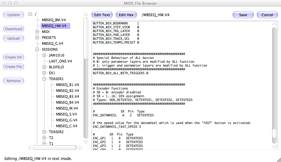
The "Update" button retrieves the directory structure. Once it has been read, files and directories can be selected in the directory tree.
Existing files can be downloaded to your computer at a speed of ca. 40..50 kb/s.
New files can be uploaded from your computer at a speed of ca. 10..20 kb/s.
The edit functions allow to modify files in text or binary (hex) format, which is really helpful for quick changes on application specific configuration files without disconnecting the SD Card from the core, or enabling the MSD driver (which would deactivate USB MIDI).
Remote-Configuration from MIOS Terminal
Some configuration values can be edited from the MIOS Terminal which is part of MIOS Studio.
Enter "help" to get a list of available commands:

In future it could be possible to edit any configuration parameter from the terminal, which might be helpful for runtime editing if MIDIO128 is used without a control surface.
Future Enhancements/Wishlist:
- all open requests have been implemented
- your request might be added here if it's easy to implement
License
This project is a DIY project licensed under TAPR NCL. A commercial release is neither planned, nor allowed! But the license allows you to build and sell up to 10 units per year (e.g. to friends) as long as the given constraints of the license are not violated.

Last update: 2026-05-17
Copyright © 1998-2026, Thorsten Klose. All rights reserved.
|