 English Version English Version 
 French Version French Version
MIDIO128 V2
Created in September 2001
NOTE: This design is expired! In 2011 MIDIO128 V3 has been developed which replaced the old version. See this page for more details.
The MIDIO128 interface enables you to drive up to 128 digital
output pins and to react on up to 128 digital input pins via MIDI.
The main intention of MIDIO128 was to midify an very old orchestrion called Frati. Find a brief description from the owner here and especially here. Someday Willy asked me for assistance because he wanted to build an interface between the orchestrion and his PC in order to record and replay the playrolls via MIDI. It wasn't much effort for me to modify my existing MIDIbox64 design for this purpose, so I just did it. :) Maybe other people are also interested in controlling instruments or electronical devices like lights, motors or just a coffee machine, so I suppose it is a good idea to publish the design.
 The Hardware The Hardware -
The Hardware design is kept very simple. Since it is based on the MBHP and is running under MIOS, it allows a lot of extensions in the future. The PIC is connected with MIDI In/Out ports and two large serial register chains: one chain for the inputs, one for the outputs. If you want to build this project, but don't need 128 IOs, you are allowed to left some shift registers (every shift register includes 8 in- or outputs). It's only important that the last input shift register is terminated with ground level (0V), so that the firmware doesn't recognize invalid values.
The Software -
The software captures all 128 inputs within a period of 1 mS. If the status of an input pin has been changed, the program searches for the predefined MIDI event in a big table and sends it out:
| Outgoing
MIDI Event
| On Input pin changes, send:
|
| 9n xx v1, 9n yy v2 |
Note Event, channel n
number xx v1 if input=0V
number yy v2 if input=5V |
| An xx v1, An yy v2 |
Aftertouch Event, channel n
number xx v1 if input=0V
number yy v2 if input=5V |
| Bn xx v1, Bn yy v2 |
Controller Event, channel n
number xx v1 if input=0V
number yy v2 if input=5V |
| Cn xx |
Program Change Event, channel n
number xx v1 if input=0V
number yy v2 if input=5V |
| Dn xx |
Channel Aftertouch Event, channel n |
| En xx v1, En yy v2 |
Pitchbender Event, channel n
number xx v1 if input=0V
number yy v2 if input=5V |
On incomming MIDI events, the software searches in another table if an output pin is assigned for the event and sets (or toggles) the pin(s) if it matches:
| Incoming
MIDI Event
| Output pin:
|
| 9n xx vv |
0V if vv=00, else 5V |
| An xx vv |
0V if vv=00, else 5V |
| Bn xx vv |
0V if vv=00, else 5V |
| Cn xx |
Two modes are configurable in the midio128.ini file:
Normal Mode: on incoming program change events, the appr. output pin will just toggle from 0V to 5V and vice versa
Alternative Mode:on incoming program change events, all output pins (assigned to program change) of the same channel will be set to 0V, but the pin which is assigned to the channel and to the program change value will be set to 5V |
| Dn xx |
Toggle: 0V if output pin currently 5V
5V if output pin currently 0V |
| En xx vv |
0V if vv=00, else 5V |
The MIDI Events for all IO pins can be configured with the mk_midio128_syx.pl script, which converts a .ini file into a SysEx Dump file. The SysEx dump has to be transfered to the MIDIO128 device via MIDI. On this way you are able to redefine the IOs every time you want without much effort and especially without re-programming the PIC. :)
Note that also the polarity of the input and output pins (negative or positive logic) can be configured in the midio128.ini file.
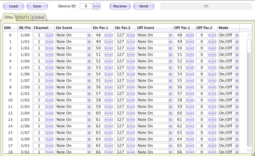
Alternatively, the configuration can be done with MIOS Studio 2:
MIDI Merger -
The MIDI Merger has to be enabled within the midio128.ini file. If activated, the MIDIO128 forwards all incoming MIDI events to the MIDI Out port. This allows you to cascade MIDI devices, i.e. to plug another MIDIO128, a MIDIbox or a keyboard behind or before the MIDIO128.
Interfacing -
Every output pin can drive up to 10-20 mA. This is enough for digital applications or LEDs. In order to control relays, lamps, motors or coffee machines, I recomment a darlington transistor driver like the ULN2803, which is cheap and handy. A datasheet can be found below.
The digital input reacts on TTL levels, this means it switches to "0" on a level below 0.5V and switches to "1" on a level above ca. 3V. Don't drive the inputs with voltages above 5V!!! See the MIDIbox64 schematic if you want to use buttons. Optocouplers help to isolate the device from critical machines.
Download
NOTE: This design is expired! In 2011 MIDIO128 V3 has been developed which replaced the old version. See this page for more details.
Last update: 2026-05-17
Copyright © 1998-2026, Thorsten Klose. All rights reserved.
|