Back to main page...
MIDIbox NG
User Manual --- First Steps
The aim of this chapter is to give you a rough oversight about the configuration of a MIDIbox NG before your are working through the details of the .NGC, .NGL and .NGR format.
 Editing Configuration Files Editing Configuration Files
First of all it makes sense to get familiar with MIOS Studio and especially the integrated MIOS Filebrowser, because it will enable you to try out changes in your MIDIbox NG setup quickly by editing the configuration files, and transfering the changes via USB-MIDI.
After power-on, your MIDIbox will always load the DEFAULT.NGC and DEFAULT.NGL file - you will see the appr. messages in the MIOS Terminal (click on the image to enlarge):
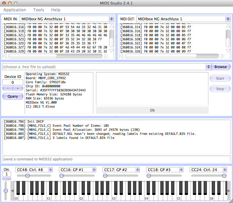
The DEFAULT files will be automatically generated if they don't exist on the connected SD Card.
By opening the MIOS Filebrowser tool in MIOS Studio, you will be able to access the files which are stored on SD Card:
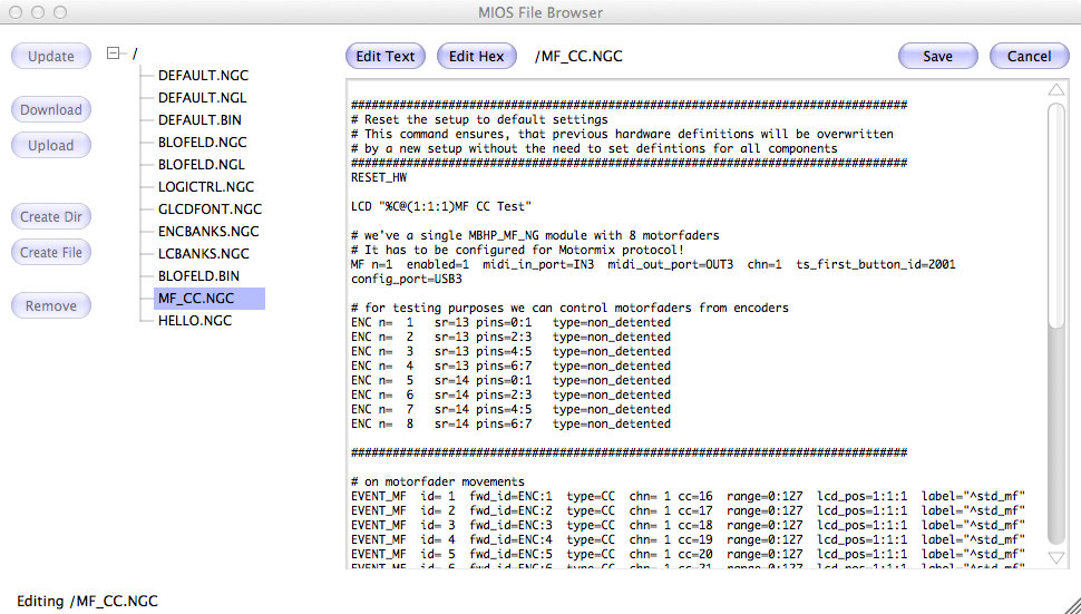
After a click on the "Update" button, files can be uploaded/downloaded from/to your harddisk - but it's especially possible to edit files without the need for an external text editor!
After transfering your changes back to the SD Card (press the SAVE button), the new file can be loaded from the MIOS Terminal with the "load" command:
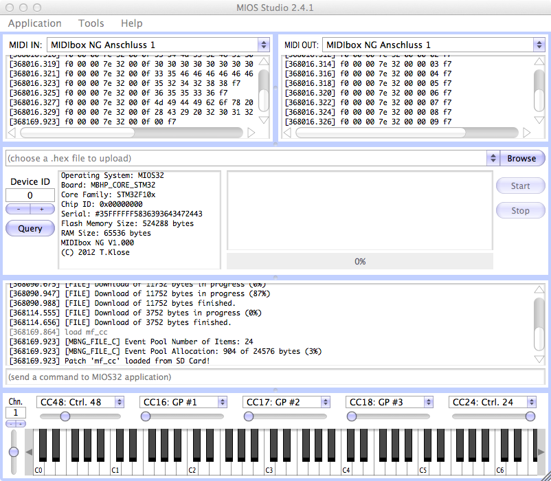 UPDATE: since MIDIbox NG V1.019 the file will be loaded automatically whenever it has been uploaded. There is no need to enter the "load" command into the MIOS Terminal after the upload anymore! :-)
The filename has to be specified without the .NGC extension.
From the MIOS Terminal it's also possible to store the current setup. So - in order to make any setup as your DEFAULT setup which will be restored after power-on, just type:
load <your-setup-file>
save default
-> done! :-)
Hello World!
Let's start with the obligatory "Hello World" example. Unfortunately this experiment will only work with a LCD which is connected to your core module.
In MIOS Filebrowser, create a new configuration file by clicking on the "Create File" button. Name it "hello.ngc", and then click on the "Update" button to re-scan the directory.
Click on the "HELLO.NGC" file and push the "Edit Text" button.
Thereafter enter following commands into this file:
RESET_HW

LCD "%CHello World!"
Click on the "Save" button. The AUTOLOAD function should automatically execute the "load hello" command after upload.
Your LCD should show the message now!
Note: detailed informations about the commands which are mentioned at this page can be found in the .NGC chapter.
This is probably also the best place to mention, that filenames (without the .NG* extension) are limited to 8 characters!
Push me!
The next experiment will work if a DIN shift register (e.g. of a MBHP_DIN or MBHP_DIO_MATRIX module is connected to J8/9 of the core module.
New: alternatively you could emulate up to 2 DIN shift registers at port J10A and J10B of a MBHP_CORE_STM32F4 module by using the DIO command. In this case, please add the two DIO commands like shown in the diocfg_1.ngc example, and connect the button(s) to J10.D0..D15
We want to generate a Note event with a button connected to the D0 pin of the first shift register. The appr. button ID is 1.
Add following command to your HELLO.NGC file:
RESET_HW

LCD "%CHello World!"

EVENT_BUTTON id=1  type=NoteOn key=36
Save the file in the filebrowser - the AUTOLOAD function will automatically execute "load hello" - this step won't be mentioned again in the steps below, because you should have good practice with this procedure now! ;-)
Push the button - it should send a Note On event with C-1, velocity 127. When you release the button, it should send C-1 with velocity 0, which equates to NoteOff.
These events are displayed in the MIDI IN monitor of MIOS Studio in hexadecimal format (in this case: 90 24 7F when pressed, and 90 24 00 when depressed) and in text format.
Push me softer!
You want to play a Note with less velocity? Then just change the range of the event:
EVENT_BUTTON id=1 type=NoteOn key=36 range=0:100
The MIDI IN monitor of MIOS Studio should now display NoteOn events with velocity 100
Changing the Channel
Events are sent to MIDI channel 1 by default. If you want to select a different channel, e.g. 3, write:
EVENT_BUTTON id=1 type=NoteOn key=36 chn=3 range=0:100
The MIDI protocol provides 16 MIDI channels....
Changing the Port
...but in some situations it might be helpful to have more!
For this purpose, MIDIbox NG provides multiple MIDI ports. With following command:
EVENT_BUTTON id=1 type=NoteOn key=36 chn=3 range=0:100 ports=0100010000000000
The MIDI event will now be send over USB2 and MIDI OUT2
Important: the MIDI IN monitor of MIOS Studio won't display this event, because it only allows to select a single input port. Select the second USB port of your MIDIbox NG to display the event, or just run a second MIOS Studio instance, or a different MIDI monitor (such as the Snoize MIDI Monitor for MacOS or MIDI-Ox for Windows).
Be Verbose!
Now we want to display the button movement on our LCD, because the "Hello World!" message gets boring.
Replace the previous EVENT definition by:
EVENT_BUTTON id=1 type=NoteOn key=36 lcd_pos=1:1:1 label="Button #%3i: %3d"
Whenever you are pushing the button, the LCD should display: Button # 1: 127
When it's released the LCD should display: Button # 1: 0
Let there be light!
This experiment requires a DOUT shift register (e.g. of a MBHP_DOUT or MBHP_DIO_MATRIX module connected to J8/9 of the core module) in addition. The anode (long leg) of the LED should be connected at D7 (the first (leftmost) DOUT output pin), the cathode (short leg) to Vs (ground).
New: alternatively you could emulate up to 2 DOUT shift registers at port J10A and J10B of a MBHP_CORE_STM32F4 module by using the DIO command. In this case, please add the two DIO commands like shown in the diocfg_2.ngc example, and connect the button(s) to J10A, and the LEDs to J10B
Beware: the J10 ports and the MBHP_DIO_MATRIX module have no series resistor for the LED! Please use a 220 Ohm resistor between Anode (long leg) and the output pin, otherwise the LED will be fried!
So much about the obligatory disclaimer... don't worry, this resistor should be already stuffed on your MBHP_DOUT module
Change the EVENT_BUTTON definition in your HELLO.NGC file as follows:
EVENT_BUTTON id=1 fwd_id=LED:1 type=NoteOn key=36 lcd_pos=1:1:1 label="Button #%3i: %3d"
The LED should turn on while you are pressing the button.
Remote me!
With the previous EVENT_BUTTON statement, play MIDI Note C1 on the virtual MIDI keyboard of MIOS Studio.
The LED should be lit whenever you are clicking with the mouse on the lower boundary of the C1 key of the virtual keyboard (velocity has to be >= 64, check this in the MIDI OUT monitor). If you click a bit more higher, the LED won't turn on because the velocity is below the half of the specified range.
In other words: the LED will only be lit if the received velocity is greater than int((127-0)/2) = 63. Velocities which are <= this value will turn off the LED.
Dim me!
While previously the LED was only switched between on and off state depending on the incoming MIDI value, now we want to control the brightness level with the received velocity value instead:
EVENT_BUTTON id=1 fwd_id=LED:1 dimmed=1 type=NoteOn key=36 lcd_pos=1:1:1 label="Button #%3i: %3d"
Only the dimmed=1 parameter has been added. The LED will change the brightness over the 0..127 value range in 16 levels.
Just for fun you could also control the brightness from a CC event:
EVENT_LED id=1 dimmed=1 type=CC cc=16
Move the "CC16" slider in MIOS Studio to check what happens! :-)
Toggle me!
Sometimes you probably want to hold the button state after the button has been pushed, and you want to turn it off by pushing it again. This toggling behaviour can be easily configured with the "button_mode" parameter:
EVENT_BUTTON id=1 fwd_id=LED:1 type=NoteOn key=36 range=0:127 button_mode=Toggle
Surprise me!
Our last experiment with a single button ends with a small surprise: change the EVENT_BUTTON statement to:
EVENT_BUTTON id=1  fwd_id=LED:1  button_mode=OnOnly \
             type=SysEx stream="0xf0 0x00 0x00 0x7e 0x32 0x00 0x0d 0x40 0x57 0x6F 0x77 0x21 0xf7" \
             lcd_pos=1:1:1 label="Button #%3i: %3d"
...and have a look at the MIOS Terminal while pressing the button... ;-)
Ok, this demonstration should also show you, that it's possible to send SysEx streams, and that multiple lines in the configuration file can be concatenated to a single command with the backslash (\) character.
MIDIbox killed the Radio Star
Let's get serious again! A typical usecase for buttons is to switch between different modes of an external device. If the mode has to be configured over a single CC event, you need to assign multiple buttons. In conjunction with LEDs it would be nice if only the LED which matches with the mode selection is lit, and that all others are off.
This behaviour can be configured with so called "Radio groups" (see also this Wikipedia article about Radio Buttons).
So, let's try it! Following experiment requires 8 buttons connected to the first DIN shift register (input D0..D7), and 8 LEDs connected to the first DOUT shift register (output D7..D0):
EVENT_BUTTON id=  1  fwd_id=LED:1  type=CC chn=1 cc=16  button_mode=OnOnly  range= 0:0   radio_group=1
EVENT_BUTTON id=  2  fwd_id=LED:2  type=CC chn=1 cc=16  button_mode=OnOnly  range= 1:1   radio_group=1
EVENT_BUTTON id=  3  fwd_id=LED:3  type=CC chn=1 cc=16  button_mode=OnOnly  range= 2:2   radio_group=1
EVENT_BUTTON id=  4  fwd_id=LED:4  type=CC chn=1 cc=16  button_mode=OnOnly  range= 3:3   radio_group=1
EVENT_BUTTON id=  5  fwd_id=LED:5  type=CC chn=1 cc=16  button_mode=OnOnly  range= 4:4   radio_group=1
EVENT_BUTTON id=  6  fwd_id=LED:6  type=CC chn=1 cc=16  button_mode=OnOnly  range= 5:5   radio_group=1
EVENT_BUTTON id=  7  fwd_id=LED:7  type=CC chn=1 cc=16  button_mode=OnOnly  range= 6:6   radio_group=1
EVENT_BUTTON id=  8  fwd_id=LED:8  type=CC chn=1 cc=16  button_mode=OnOnly  range= 7:7   radio_group=1
They are all assigned to the same radio group 1 (note that up to 63 groups are available!).
Now push the buttons one after another. Only the LED of the pressed buttons should be activated, all others will be turned off.
Next step: send a CC16 event from MIOS Studio (take a slider above the virtual keyboard). The LEDs should change their state corresponding to the received value.
Radio LEDs
The same can be done without buttons, but only with LEDs. And it's also possible to select larger value ranges for a radio group!
So, let's assume that 8 additional LEDs are connected to the second DOUT shift register, output D7..D0. We want to select the LED depeding on the incoming CC1 (modulation wheel) value. Just write:
EVENT_LED    id=  9                type=CC chn=1 cc= 1  range= 0:9  radio_group=2
EVENT_LED    id= 10                type=CC chn=1 cc= 1  range=10:19 radio_group=2
EVENT_LED    id= 11                type=CC chn=1 cc= 1  range=20:29 radio_group=2
EVENT_LED    id= 12                type=CC chn=1 cc= 1  range=30:39 radio_group=2
EVENT_LED    id= 13                type=CC chn=1 cc= 1  range=40:49 radio_group=2
EVENT_LED    id= 14                type=CC chn=1 cc= 1  range=50:59 radio_group=2
EVENT_LED    id= 15                type=CC chn=1 cc= 1  range=60:69 radio_group=2
EVENT_LED    id= 16                type=CC chn=1 cc= 1  range=70:79 radio_group=2
...and move the slider for "CC1: ModWheel" in MIOS Studio to select the different LEDs. :-)
Rotate me!
We are coming to the next control element: a Rotary Encoder.
MIOS32 supports different type of encoders, we can mainly differentiate between "detented" and "non-detented". For detented encoders we also have to differ between various types, mainly depending on the state where it makes "click" ;-)
The configuration of an encoder has to be done independent from the EVENT definition. E.g. take following configuration as an example:
ENC n=  1   sr=3 pins=0:1   type=non_detented
ENC n=  2   sr=3 pins=2:3   type=non_detented
ENC n=  3   sr=3 pins=4:5   type=non_detented
ENC n=  4   sr=3 pins=6:7   type=non_detented
ENC n=  5   sr=4 pins=0:1   type=non_detented
ENC n=  6   sr=4 pins=2:3   type=non_detented
ENC n=  7   sr=4 pins=4:5   type=non_detented
ENC n=  8   sr=4 pins=6:7   type=non_detented
In this example it's assumed, that 8 rotary encoders are connected to the third and fourth DIN shift register of your MBHP_DINX4 module. Of course, you are free to use different DIN SRs for this, please adapt your configuration accordingly by changing the "sr=<shift-register-number>" assignment.
Channel A and B of the encoder have to be connected to pin D0/D1, D2/D3, D4/D5 or D6/D7. The third pin has to be connected to ground. Some encoders have the ground at the middle pin, some others at the left or right pin - please consult the datasheet of the encoder that you bought!
Without EVENT_ENC definition your encoder won't generate any MIDI event. But you will already be able to check, if encoder movements are notified by MIOS32. For this purpose, please activate the debug mode of MIDIbox NG in the MIOS Terminal:
set debug on
When you are now moving the encoder, you should get debugging messages such as:
...
[472675.962] MBNG_ENC_NotifyChange(0, 1)
[472675.962] No event assigned to ENC id=1
[472676.035] MBNG_ENC_NotifyChange(0, 1)
[472676.035] No event assigned to ENC id=1
[472676.061] MBNG_ENC_NotifyChange(0, 1)
[472676.061] No event assigned to ENC id=1
...
on clockwise movements, and:
...
[472692.954] MBNG_ENC_NotifyChange(0, -1)
[472692.954] No event assigned to ENC id=1
[472692.969] MBNG_ENC_NotifyChange(0, -1)
[472692.969] No event assigned to ENC id=1
[472693.040] MBNG_ENC_NotifyChange(0, -1)
[472693.040] No event assigned to ENC id=1
...
on counter-clockwise movements of the first encoder (MIOS32 starts to count encoders from #0)
This debugging mode already allows you to debug your configuration. E.g. if you are using a detented encoder, try:
- enc_mode=detented1
- or enc_mode=detented2
- or enc_mode=detented3
and check if the increments are notified correctly after each "click".
If the increments are inversed (-1 on clockwise movements), then you've probably swapped the connections between channel A and B of the encoder. In this case, please fix your hardware connections (this can't be changed in the configuration).
Encoder: send MIDI - now!
It's time to assign MIDI events to the encoders:
EVENT_ENC id=1  type=CC chn= 1 cc= 16
EVENT_ENC id=2  type=CC chn= 1 cc= 17
EVENT_ENC id=3  type=CC chn= 1 cc= 18
EVENT_ENC id=4  type=CC chn= 1 cc= 19
EVENT_ENC id=5  type=CC chn= 1 cc= 20
EVENT_ENC id=6  type=CC chn= 1 cc= 21
EVENT_ENC id=7  type=CC chn= 1 cc= 22
EVENT_ENC id=8  type=CC chn= 1 cc= 23
Your encoders will now send CC#16 .. CC#23 events, which should be displayed in the MIDI IN monitor of MIOS Studio!
The big advantage of those encoders is, that they can take over incoming MIDI values, and modify them without the danger of "value jumps" when the encoder is moved again to modify the value (in other words: it will be on-synch to the remote device if it sends its own value changes as well).
So, the next experiment will be, to send a CC#16 event to your MIDIbox NG, e.g. with the slider above the virtual keyboard in MIOS Studio.
E.g. move the slider so that it sends CC#16 = 64 (check this with the MIDI OUT monitor of MIOS Studio).
Now move the first encoder: it should increment/decrement from this received value!
Display me!
You already own a LCD? Fine - the next experiment will display some useful informations on the LCD instead of the static "Hello World!" string:
EVENT_ENC id=1  type=CC chn= 1 cc= 16  lcd_pos=1:1:1  label="ENC #%3i    %3d%B"
EVENT_ENC id=2  type=CC chn= 1 cc= 17  lcd_pos=1:1:1  label="ENC #%3i    %3d%B"
EVENT_ENC id=3  type=CC chn= 1 cc= 18  lcd_pos=1:1:1  label="ENC #%3i    %3d%B"
EVENT_ENC id=4  type=CC chn= 1 cc= 19  lcd_pos=1:1:1  label="ENC #%3i    %3d%B"
EVENT_ENC id=5  type=CC chn= 1 cc= 20  lcd_pos=1:1:1  label="ENC #%3i    %3d%B"
EVENT_ENC id=6  type=CC chn= 1 cc= 21  lcd_pos=1:1:1  label="ENC #%3i    %3d%B"
EVENT_ENC id=7  type=CC chn= 1 cc= 22  lcd_pos=1:1:1  label="ENC #%3i    %3d%B"
EVENT_ENC id=8  type=CC chn= 1 cc= 23  lcd_pos=1:1:1  label="ENC #%3i    %3d%B"
If you are confused about the strange "format specifiers" (starting with %), have a look into the .NGC format specification, search for "label=<string>"
Toy me!
Let's play a bit with the labels. The example above overwrites the previous string whenever a different encoder is moved. But what if you want to get an oversight over all encoders - at least a vertical meter for each encoder?
Try this one:
EVENT_ENC id=1  type=CC chn= 1 cc= 16  lcd_pos=1:1:1  label="ENC #%3i    %3d@(1:1:2)%B"
EVENT_ENC id=2  type=CC chn= 1 cc= 17  lcd_pos=1:1:1  label="ENC #%3i    %3d@(1:2:2)%B"
EVENT_ENC id=3  type=CC chn= 1 cc= 18  lcd_pos=1:1:1  label="ENC #%3i    %3d@(1:3:2)%B"
EVENT_ENC id=4  type=CC chn= 1 cc= 19  lcd_pos=1:1:1  label="ENC #%3i    %3d@(1:4:2)%B"
EVENT_ENC id=5  type=CC chn= 1 cc= 20  lcd_pos=1:1:1  label="ENC #%3i    %3d@(1:5:2)%B"
EVENT_ENC id=6  type=CC chn= 1 cc= 21  lcd_pos=1:1:1  label="ENC #%3i    %3d@(1:6:2)%B"
EVENT_ENC id=7  type=CC chn= 1 cc= 22  lcd_pos=1:1:1  label="ENC #%3i    %3d@(1:7:2)%B"
EVENT_ENC id=8  type=CC chn= 1 cc= 23  lcd_pos=1:1:1  label="ENC #%3i    %3d@(1:8:2)%B"
This will display the state of each encoder at the second LCD line - we selected it with the @(<lcd>:<X>:<Y>) specifier.
Toy me remotely!
You may have already noticed, that the LCD message isn't updated when the encoder value is changed from external (e.g. from a slider in MIOS Studio). The reason is, that incoming MIDI events won't trigger a LCD message by default (because this could be unwanted under certain situations).
In order to update the LCD also in such situations, add the "fwd_to_lcd=1" parameter to your EVENT_* definition:
EVENT_ENC id=1  fwd_to_lcd=1  type=CC chn= 1 cc= 16  lcd_pos=1:1:1  label="ENC #%3i    %3d@(1:1:2)%B"
EVENT_ENC id=2  fwd_to_lcd=1  type=CC chn= 1 cc= 17  lcd_pos=1:1:1  label="ENC #%3i    %3d@(1:2:2)%B"
EVENT_ENC id=3  fwd_to_lcd=1  type=CC chn= 1 cc= 18  lcd_pos=1:1:1  label="ENC #%3i    %3d@(1:3:2)%B"
EVENT_ENC id=4  fwd_to_lcd=1  type=CC chn= 1 cc= 19  lcd_pos=1:1:1  label="ENC #%3i    %3d@(1:4:2)%B"
EVENT_ENC id=5  fwd_to_lcd=1  type=CC chn= 1 cc= 20  lcd_pos=1:1:1  label="ENC #%3i    %3d@(1:5:2)%B"
EVENT_ENC id=6  fwd_to_lcd=1  type=CC chn= 1 cc= 21  lcd_pos=1:1:1  label="ENC #%3i    %3d@(1:6:2)%B"
EVENT_ENC id=7  fwd_to_lcd=1  type=CC chn= 1 cc= 22  lcd_pos=1:1:1  label="ENC #%3i    %3d@(1:7:2)%B"
EVENT_ENC id=8  fwd_to_lcd=1  type=CC chn= 1 cc= 23  lcd_pos=1:1:1  label="ENC #%3i    %3d@(1:8:2)%B"
Now move the sliders in MIOS Studio and watch the LCD output! :-)
Ring me!
The next step - and this is really an advanced one - will be to use LED Rings for displaying the state of each rotary encoder.
The (non-existing) Hardware Chapter describes, how the circuitry looks like.
Actually it doesn't matter, if you are building the circuit based on the given schematic, or customize it, e.g. only for 8 LED Rings, or with a different number of LEDs per ring.
The entry point to configure LED Rings is the DOUT_MATRIX command. It specifies the DOUT shift registers, which are used to access the LEDs in a matrix configuration. Matrix is good for such a usecase, because it saves a lot of digital output pins. The (small) drawback is, that LEDs are activated time multiplexed, which means that they are not so bright as if they would be driven directly (permanently) from a digital output pin. However, by using low-current LEDs this can be easily compensated. See it as an advantage: time multiplexing saves power (you still want to supply your MIDIbox NG via USB...)
So, in following configuration example we assume a 16 LED Ring configuration, because this is the most common one that I used in previous projects like the MIDIbox16E:
# LEDring configuration
DOUT_MATRIX n= 1   rows=16 sr_dout_sel1= 1 sr_dout_sel2= 2  sr_dout_r1= 3 sr_dout_r2= 4
Today we would prefer to use Fairlightiii's premade PCB solution instead - more informations about this once I get my hands on the PCBs! :-)
Anyhow, as you can see in the definitions above, the matrix allocates four DOUT shift registers to select the 16 rows, and to output the pattern. The pattern is predefined for 11 LEDs, but could also be changed for any number of LEDs with the LED_MATRIX_PATTERN command.
Now let's try following .NGC file - this is a copy&paste of my complete setup (for the case that you lost the thread... ;-)
It might be necessary that you adapt the shift register (sr*=) definitions to your hardware, depending on which shift registers (SRs) your encoders and LED Rings are located!
RESET_HW

LCD "%CHello"

# Encoder configuration
ENC n=  1   sr= 5  pins=0:1   type=non_detented
ENC n=  2   sr= 5  pins=2:3   type=non_detented
ENC n=  3   sr= 5  pins=4:5   type=non_detented
ENC n=  4   sr= 5  pins=6:7   type=non_detented
ENC n=  5   sr= 6  pins=0:1   type=non_detented
ENC n=  6   sr= 6  pins=2:3   type=non_detented
ENC n=  7   sr= 6  pins=4:5   type=non_detented
ENC n=  8   sr= 6  pins=6:7   type=non_detented
ENC n=  9   sr= 7  pins=0:1   type=non_detented
ENC n= 10   sr= 7  pins=2:3   type=non_detented
ENC n= 11   sr= 7  pins=4:5   type=non_detented
ENC n= 12   sr= 7  pins=6:7   type=non_detented
ENC n= 13   sr= 8  pins=0:1   type=non_detented
ENC n= 14   sr= 8  pins=2:3   type=non_detented
ENC n= 15   sr= 8  pins=4:5   type=non_detented
ENC n= 16   sr= 8  pins=6:7   type=non_detented

# LEDring configuration
DOUT_MATRIX n= 1   rows=16 sr_dout_sel1= 1 sr_dout_sel2= 2  sr_dout_r1= 3 sr_dout_r2= 4

# Encoder events
EVENT_ENC id= 1  fwd_id=LED_MATRIX:1   fwd_to_lcd=1  type=CC chn= 1 cc= 16  label="ENC #%3i    %3d@(1:1:2)%B"
EVENT_ENC id= 2  fwd_id=LED_MATRIX:2   fwd_to_lcd=1  type=CC chn= 1 cc= 17  label="ENC #%3i    %3d@(1:2:2)%B"
EVENT_ENC id= 3  fwd_id=LED_MATRIX:3   fwd_to_lcd=1  type=CC chn= 1 cc= 18  label="ENC #%3i    %3d@(1:3:2)%B"
EVENT_ENC id= 4  fwd_id=LED_MATRIX:4   fwd_to_lcd=1  type=CC chn= 1 cc= 19  label="ENC #%3i    %3d@(1:4:2)%B"
EVENT_ENC id= 5  fwd_id=LED_MATRIX:5   fwd_to_lcd=1  type=CC chn= 1 cc= 20  label="ENC #%3i    %3d@(1:5:2)%B"
EVENT_ENC id= 6  fwd_id=LED_MATRIX:6   fwd_to_lcd=1  type=CC chn= 1 cc= 21  label="ENC #%3i    %3d@(1:6:2)%B"
EVENT_ENC id= 7  fwd_id=LED_MATRIX:7   fwd_to_lcd=1  type=CC chn= 1 cc= 22  label="ENC #%3i    %3d@(1:7:2)%B"
EVENT_ENC id= 8  fwd_id=LED_MATRIX:8   fwd_to_lcd=1  type=CC chn= 1 cc= 23  label="ENC #%3i    %3d@(1:8:2)%B"
EVENT_ENC id= 9  fwd_id=LED_MATRIX:9   fwd_to_lcd=1  type=CC chn= 1 cc= 24  label="ENC #%3i    %3d@(1:9:2)%B"
EVENT_ENC id=10  fwd_id=LED_MATRIX:10  fwd_to_lcd=1  type=CC chn= 1 cc= 25  label="ENC #%3i    %3d@(1:10:2)%B"
EVENT_ENC id=11  fwd_id=LED_MATRIX:11  fwd_to_lcd=1  type=CC chn= 1 cc= 26  label="ENC #%3i    %3d@(1:11:2)%B"
EVENT_ENC id=12  fwd_id=LED_MATRIX:12  fwd_to_lcd=1  type=CC chn= 1 cc= 27  label="ENC #%3i    %3d@(1:12:2)%B"
EVENT_ENC id=13  fwd_id=LED_MATRIX:13  fwd_to_lcd=1  type=CC chn= 1 cc= 28  label="ENC #%3i    %3d@(1:13:2)%B"
EVENT_ENC id=14  fwd_id=LED_MATRIX:14  fwd_to_lcd=1  type=CC chn= 1 cc= 29  label="ENC #%3i    %3d@(1:14:2)%B"
EVENT_ENC id=15  fwd_id=LED_MATRIX:15  fwd_to_lcd=1  type=CC chn= 1 cc= 30  label="ENC #%3i    %3d@(1:15:2)%B"
EVENT_ENC id=16  fwd_id=LED_MATRIX:16  fwd_to_lcd=1  type=CC chn= 1 cc= 31  label="ENC #%3i    %3d@(1:16:2)%B"
This setup:
- configures the encoders and LED Ring hardware
- sends cc=16..31 whenever an encoder has been moved
- receives cc=16..31 to update the encoder value
- forwards the sent/received encoder value to the LED Ring
- and forwards the sent/received encoder value to the LCD
Bank me!
You want to get more for the same price? Let's bank the encoders! :-)
# Example for Encoder 1
EVENT_ENC id= 1  hw_id=1  bank=1  fwd_id=LED_MATRIX:1   fwd_to_lcd=1  \
                                  type=CC chn= 1 cc= 16  lcd_pos=1:1:1  label="ENC #%3i    %3d@(1:1:2)%B"

EVENT_ENC id=17  hw_id=1  bank=2  fwd_id=LED_MATRIX:1   fwd_to_lcd=1  \
                                  type=CC chn= 1 cc= 32  lcd_pos=1:1:1  label="ENC #%3i    %3d@(1:1:2)%B"

EVENT_ENC id=33  hw_id=1  bank=3  fwd_id=LED_MATRIX:1   fwd_to_lcd=1  \
                                  type=CC chn= 1 cc= 48  lcd_pos=1:1:1  label="ENC #%3i    %3d@(1:1:2)%B"

EVENT_ENC id=49  hw_id=1  bank=4  fwd_id=LED_MATRIX:1   fwd_to_lcd=1  \
                                  type=CC chn= 1 cc= 64  lcd_pos=1:1:1  label="ENC #%3i    %3d@(1:1:2)%B"
These commands will map the first hardware encoder (hw_id=1) to the EVENT_ENC elements 1, 17, 33 and 49, which will send different CC numbers.
You will need 4 buttons to switch between the banks - this is achieved by using so called "Meta Events" which don't issue MIDI output, but trigger internal functions instead:
EVENT_BUTTON id=  1  type=Meta   meta=SetBank button_mode=OnOnly range=1:1  lcd_pos=1:17:1 label="Bnk%q"
EVENT_BUTTON id=  2  type=Meta   meta=SetBank button_mode=OnOnly range=2:2  lcd_pos=1:17:1 label="Bnk%q"
EVENT_BUTTON id=  3  type=Meta   meta=SetBank button_mode=OnOnly range=3:3  lcd_pos=1:17:1 label="Bnk%q"
EVENT_BUTTON id=  4  type=Meta   meta=SetBank button_mode=OnOnly range=4:4  lcd_pos=1:17:1 label="Bnk%q"
A complete configuration example can be found in the GIT repository: encbanks.ngc
This setup:
- configures the encoders and LED Ring hardware
- sends cc=16..31, cc=32..47, cc=48..63, cc=64..79 depending on the bank selection whenever an encoder has been moved
- always receives cc=16..79 independent from the bank selection. The LED Rings will be updated according to the visible bank range
- forwards the sent/received encoder value to the LED Ring
- and forwards the sent/received encoder value to the LCD within the visible bank range
So, this is actually what I started a century ago with the MIDIbox 16E project. But with the MIDIbox NG approach we got a much more flexible solution - not to mention the advantages of USB-MIDI, OSC, SD Card as storage, no need to recompile the firmware on configuration changes, grouped Buttons/LEDs, support for NRPN and SysEx, more shift registers, more LCDs, even graphical LCDs (see below - in future - implemented but not documented at this place yet), etc, etc...
To be continued...
...soon!

Last update: 2026-05-17
Copyright © 1998-2026, Thorsten Klose. All rights reserved.
|