MIDI Interface Troubleshooting Guide
This guide has been written for troubleshooting the MIDI connections between a PIC based MBHP_CORE module and your Windows/Linux PC or Mac. It is a collection of issues reported by users in the past years, and has been overworked with the launch of MIOS Studio MkII to consider the improved debugging capabilities of this tool.
Please be aware that previous troubleshooting tips which were mentioned in the MIDIbox Forum are partly obsolete (like trying the expired hex2syx.pl script) or won't work anymore (such as Java based MIOS Studio under newer MacOS versions w/o commercial MIDI driver).
Also the different steps of the test procedure have been rearranged based on experiences in the past. Now we are starting with the most simple checks to ensure that the basic infrastructure is working before going deeper into details like voltage checks, which are mostly not required anymore if you found the error in your MIDI cabling or PC/Mac setup.
Please don't ask for help in the forum before you haven't worked through this guide. If the guide doesn't cover your issue, please take reference to the steps you already tried - this will help a lot to understand your situation and usually will lead to a faster solution. Previously uncovered issues will be added to this guide to keep it so complete as possible.
First tries to contact the PIC via MIDI
A proper MIDI link to your computer is essential for a successful upload of MIOS and MIOS applications. If you purchased a PIC directly from an electronic shop, you will have to burn the MIOS Bootloader before with a PIC Programmer, if you purchased the PIC from Mike, the bootloader is already preprogrammed (so that a PIC programmer isn't required), and if you purchased it from SmashTV, MIOS is preinstalled in addition (advantage: this already allows you to test a LCD without installing MIOS).
In any case, you have to ensure that MIOS is running before uploading a MIOS application. MIOS Studio helps you to test this via MIDI even if no LCD is connected.
Start MIOS Studio and select the IN (1) and OUT (2) port of the MIDI interface to which you core module is connected:
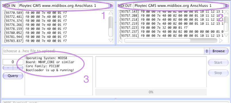
MIOS Studio will automatically try to contact the PIC whenever a new MIDI port has been selected, and determine the run state.
You can repeat this check by pressing the Query button.
In the snapshot above, MIOS hasn't been installed yet (or if the core has been queried within 3 seconds after power-on) - the bootloader will be detected. (3)
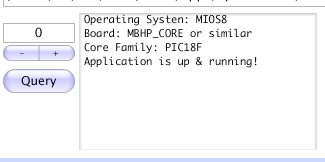
After a successful MIOS installation, the application should be detected instead:
Next steps:
- Application is up & running: congratulations! MIOS has been installed successfully and the bidirectional MIDI communication is working. Stop reading here, and start to upload the .hex file of an application (e.g. downloaded from the MIOS Download page).
- Only bootloader detected: it seems that MIOS hasn't been installed yet, upload the latest release which can be found at the MIOS Download page.
- Only bootloader detected, but you are sure that MIOS was installed before: maybe the application crashes due to a programming error? Report this issue to the guy who implemented the application, and try to get an updated version. The new application can be uploaded via bootloader as well.
- Only bootloader detected, and you are unsure if MIOS was installed before: just upload MIOS again, it's fast and doesn't hurt!
- Neither Bootloader nor Application detected: continue reading the next chapters.
Checking the MIDI Interface via Loopback
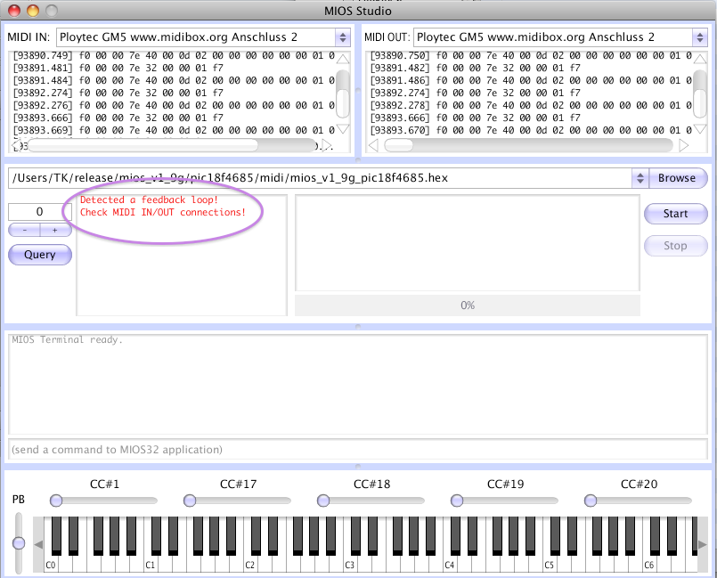
- TEST PC1: ensure that the MIDI interface of your computer is working: loopback the MIDI Out of your computer to the MIDI In of your computer with a MIDI cable. Press the Query button, a loopback should be detected as shown here.
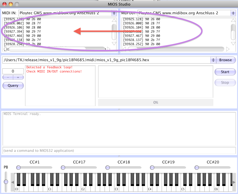
Send some MIDI notes with the virtual keyboard; MIDI events displayed by the OUT monitor should also be displayed by the IN monitor as shown here.
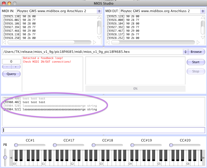
Now test SysEx transfers by typing some arbitrary strings into the MIOS terminal input window as shown here (note that the MIOS terminal itself is mostly only supported by MIOS32 - but it's a nice debugging help in this situation.
Next steps:
- Loopback not working at all: there seems to be a problem with your MIDI cable, with the MIDI interface or your the MIDI interface driver (google for solutions).
- MIDI Notes are received, but no MIOS Terminal messages: it seems that your MIDI interface doesn't handle SysEx messages correctly. See also the Blacklist. Sometimes it helps to update the driver.
- Loopback is working in all cases: it seems that your MIDI interface works reliable, continue with the next chapter
Checking MIDI Connections between Computer and Core
- TEST MIDI1: check the MIDI port configuration - are the correct ports selected in MIOS Studio? Important: MIDI In of the core has to be connected to the MIDI Out of your interface, and MIDI Out of the core has to be connected to the MIDI In of your interface (mbhp_core_midi_crosslink.gif).
- TEST MIDI2: put the PIC out of the socket and loopback the MIDI IO ports at the Rx/Tx pins like demonstrated in mbhp_core_extract_io_loopback.gif. The core module has to be powered for this test! Repeat the loopback test of the previous chapter.
Next steps:
- Loopback is working: MIDI In and Out port of your core module are working. The problem is probably related to your PIC or soldering work. Continue at the "Core Tests" chapter.
- Loopback not working anymore: there seems to be a problem with your core module which requires further analysis - continue with the next chapter
Checking the MIDI Output of your Core Module
- TEST OUT1: Powercycle (Off/On) the core supply. The core should send one or more upload requests to MIOS Studio, which will be displayed in the MIDI IN window as "f0 00 00 7e 40 <device-id> 01 f7", such as "f0 00 00 7e 40 00 01 f7" - if a different device ID is displayed, change it in the selection above the query button and try to query the core again.
- TEST OUT2: Connect a LED to your MIDI Out port and check if it flickers: mbhp_core_extract_out_led.gif
- TEST OUT3: Somebody noticed in the forum, that the MIDI Out of his core module didn't work because of an "incompatibility issue" with the bench supply he used and the switching PSU of his PC. The solution was to disconnect the middle pin of J12 (ground line of MIDI Out port)
Next steps:
- LED flickers: the PIC is running and the MIDI Out port of your core module is working, continue with checking the MIDI Input circuit.
- LED doesn't flicker: the problem is probably related to your soldering work. Continue at the "Core Tests" chapter.
Checking the MIDI Input of your Core Module
- TEST IN1A: Check the resistor values at the MIDI In Port: R11=220 Ohm (resistor code: red-red-brown), R6=1.2kOhm (brown-red-red), R5=5.6kOhm (Green-Blue-Red).
- TEST IN1B: Check that the 6N138 optocoupler is put with the correct pin orientation into the socket! Pin #1 (marked with a notch) shows into the direction of J11!
Note that the optocoupler could be damaged if you are trying the wrong pin orientation!
- TEST IN2: Check the polarity of your MIDI plugs again: mbhp_core_extract_midi_plugs.gif - maybe the two pins of the MIDI In port are swapped?
- TEST IN3: solder two cables to the bottom side of the core module like shown in mbhp_core_midiin_debug.gif. The LED should be lit (take the polarity of the LED into account, the short leg is the cathode and has to be connected via a resistor to Vss). As long as single MIDI events are received, you won't notice a difference, but with a continuous SysEx stream the LED should begin to flicker.
Note:as long as the LED is connected directly to the Rx pin, the PIC will *not* receive the MIDI data due to the power consumption of the LED. This method is only usefull to test if the MIDI signal is available at the Rx pin.
- TEST IN4: if the LED isn't lit, connect the anode to the optocoupler (Pin IC2:6). If it still isn't lit, connect the anode with the +5V rail of the optocoupler (Pin IC2:8)
- TEST IN5: If this doesn't help you to detect the error, continue with the next step - see mbhp_core_midiin_debug2.gif - in this configuration the LED should only be lit when MIDI data is received. The more MIDI events are received a time, the brigther the LED. If the LED isn't lit, check the polarity of the protection diode D1 before the optocoupler (again...). Also check the polarity of the MIDI cable (again...).
- TEST IN6: Standalone test for the optocoupler: mbhp_core_extract_opto_test.gif
- TEST IN7: A second standalone test for the optocoupler, this time the optocoupler isn't plugged in the core module: mbhp_core_opto_test.gif
Disconnect the LED after the tests, otherwise the PIC won't receive MIDI data!.
Next steps:
- Any test fails: the problem is probably related to your soldering work. Continue at the "Core Tests" chapter.
Core Tests
- TEST CORE1: ensure that you've stuffed a 10 MHz crystal (parallel cut) to your PIC18F core module
- TEST CORE2: n/a anymore.
- TEST CORE3: Check it visually for bad solderings or missed junctions
- TEST CORE4: Check Vdd of the power supply like shown here: mbhp_core_extract_measuring_vdd.gif
- TEST CORE5: Check the ground of the power supply like shown here: mbhp_core_extract_measuring_gnd.gif
- TEST CORE6: Check the polarity of your MIDI plugs: mbhp_core_extract_midi_plugs.gif
- TEST CORE7: Check the polarity of the protection diode D1: mbhp_core_extract_midi_d1.gif
- TEST CORE8: Check the resistor values at the MIDI Out Port: R8 and R7=220 Ohm (resistor code: red-red-brown)
- TEST CORE9: n/a anymore.
- TEST CORE10: If you notice a lot of request messages like shown in this snapshot, then there is a short circuit between the Rx and Tx pin of the PIC. Check the tracks which are routed from the MIDI-Link port J11 to the Rx/Tx pins for direct connections (see the layout and schematic), you could scratch with a screw driver between the tracks to ensure that they are not connected together.
- TEST CORE11: The code upload can also fail if no, or a too small bypass cap is connected to the power rails of the PIC. A possible effect is, that for example "F0 F0 F0 F0 7E F0 00 01" will be sent by the PIC instead of the proper SysEx string "F0 00 00 7E 40 ... F7". Another effect could be, that something is received by your MIDI interface, but not displayed by the MIDI monitor because of the invalid MIDI event structure. This all can happen even when the IO and Software loopback test which is discussed below is passing,
If this happens, check that the 2200 uF cap (C5 of the core module) is soldered properly. If you are unsure about the state of the cap, since you've re-used it from an old device, try another one.
If you are using the optimized PSU for MIDIbox SID, bypass the outer pins of the (not mounted) 7805, so that C5 has contact with the +5V/Ground rails (see also mbhp_4xsid_c64_psu_optimized.pdf)!
Addendum for Experts who own a PIC programmer
- TEST SW1: The bootstrap loader is normaly sufficient for MIDI In and Out Port checks, but under special circumstances an alternative firmware makes sense to get a better understanding about the root cause for a non-working code upload.
The software implemented loopback test is a .hex file can be programmed directly into the PIC.
Connect the MIDI OUT of your MIDIbox with the MIDI IN of your computer and the MIDI IN of your MIDIbox with the MIDI OUT of your computer. Turn on your MIDIbox and try the loopback tests "TEST MIDI2", but w/o bridging Rx/Tx. Note: the RD4 pin (CORE::J14) toggles on each incoming MIDI byte, this is a nice additional debugging help.
- TEST SW2: (only relevant if you've programmed the bootloader with your own PIC programmer): some PIC programmers are not able to modify the ID field, which specifies the MIOS device ID, the LCD type and especially the to-COM option (alternative baudrate). This wouldn't be a problem as long as the ID is completely zero (common case), but unfortunately the ID field is FFFFFFFFFFFFFFFF by default. This program fixes the ID field, details are described in the main.asm header
In any case...
Good Luck!

Last update: 2026-05-17
Copyright © 1998-2026, Thorsten Klose. All rights reserved.
|